

Next:
III. Satellite Orbital Motion
Up: II. Global
Positioning System
Previous:
2.3 Control Segment

- NAVSTAR-GPS is a one-way ranging system (two clock errors
involved, pseudoranges): we need at least 4 pseudoranges, to
determine 4-D
user position (x,y,z,dt), knowing
the satellite position-clocks.
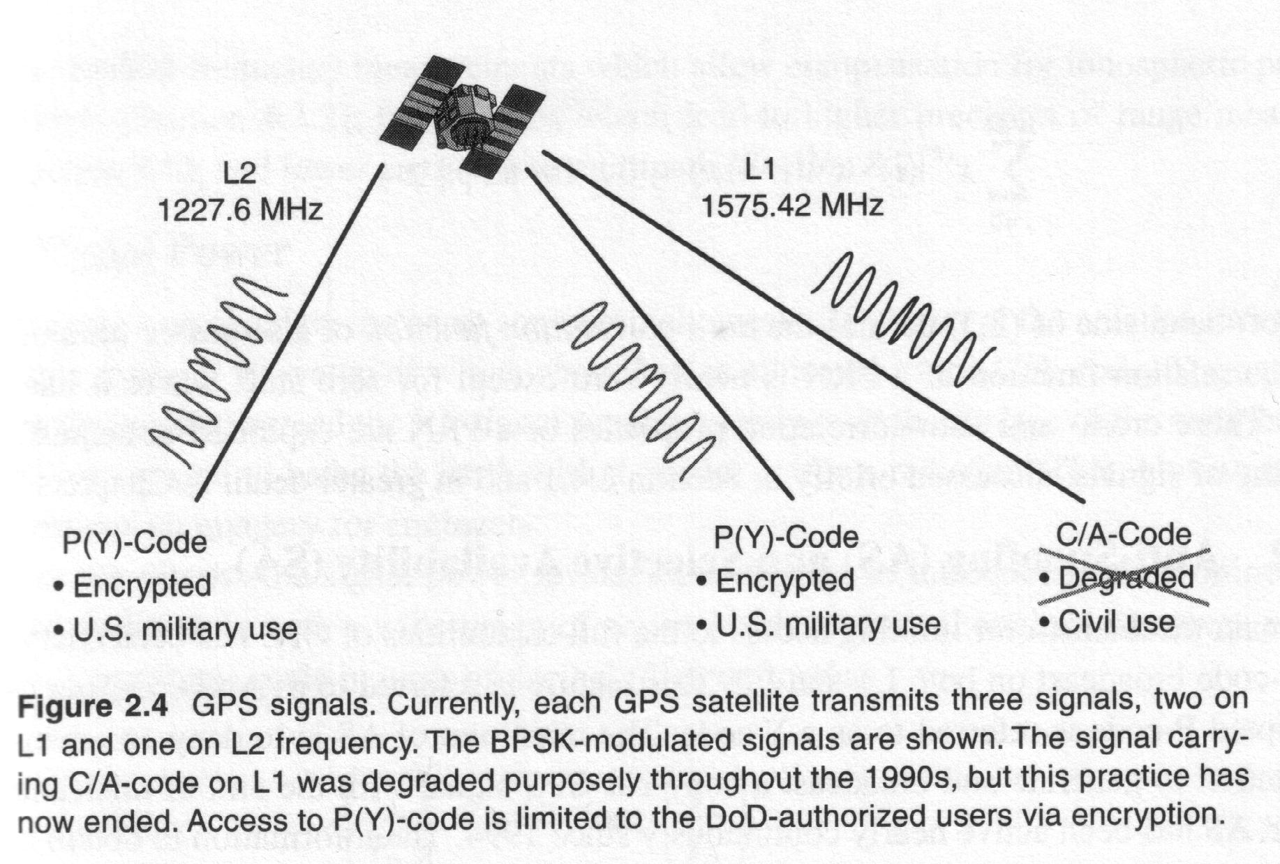
- GPS signals: the carriers are modulated with pseudorandom
noise
codes (PRN): binary sequence -apparently random- that can be
identified.
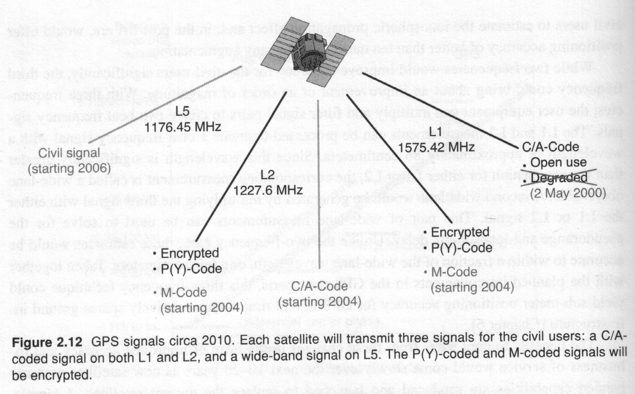
- Two public (civilian) codes:
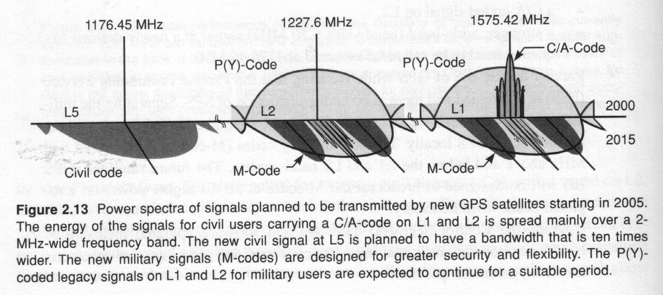
- P-code (protected, precision) available at L1,L2 (P1,P2):
- Chipping rate of 10.23 MHz ("wavelenght"
of 30 m).
- It is a sequence that only repeats each 266 days (38
weeks).
- Each satellite has its own week-segment of the code
(starting
at 0h Sunday)
- The codes share the same frequency, code division
multiple access, CDMA).
- By the moment, the P-codes P1,P2 are encrypted for
non-authorized
users to Y1,Y2 (Antispoofing).
- But the -unknown- codes Y1,Y2 are the
same for both frequencies, so some civilian receivers generates with
C/A
and Y2-Y1 the
 code in L2.
- C/A-code (clear/adquisition or coarse/adquisition) only
available at
L1:
- Chipping rate of 1.023 MHz ("wavelenght"
of 300 m).
- It repeats each 1 ms and it is syncronized with P1.
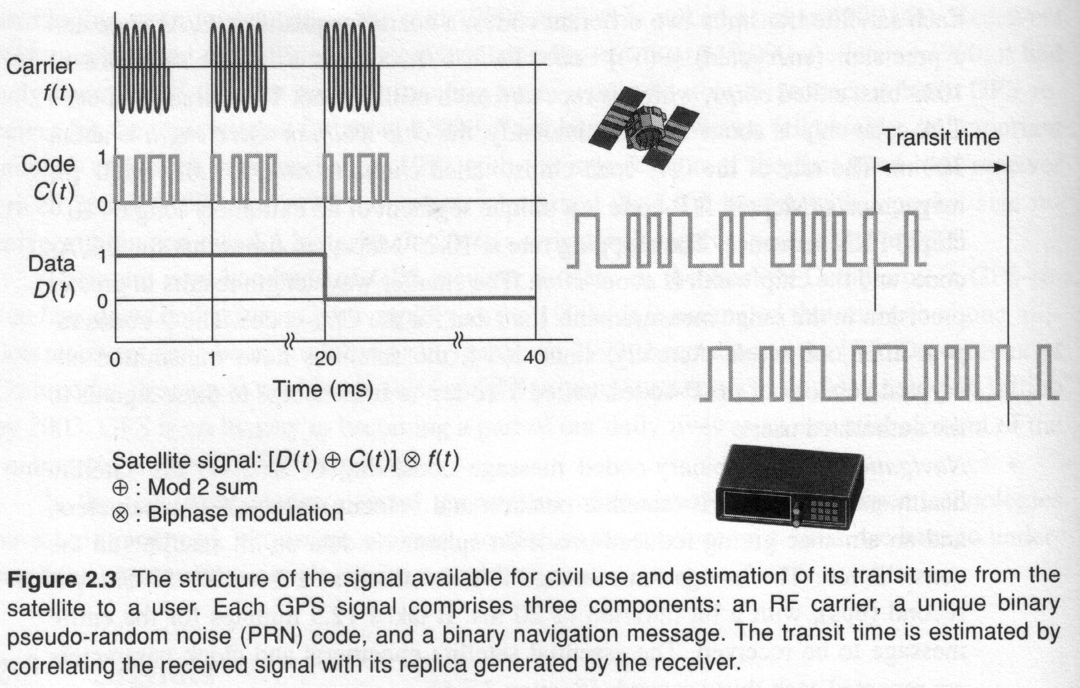
- The code observation: correlating the incoming
signal with
the user's copy of the code sequence in the receiver.
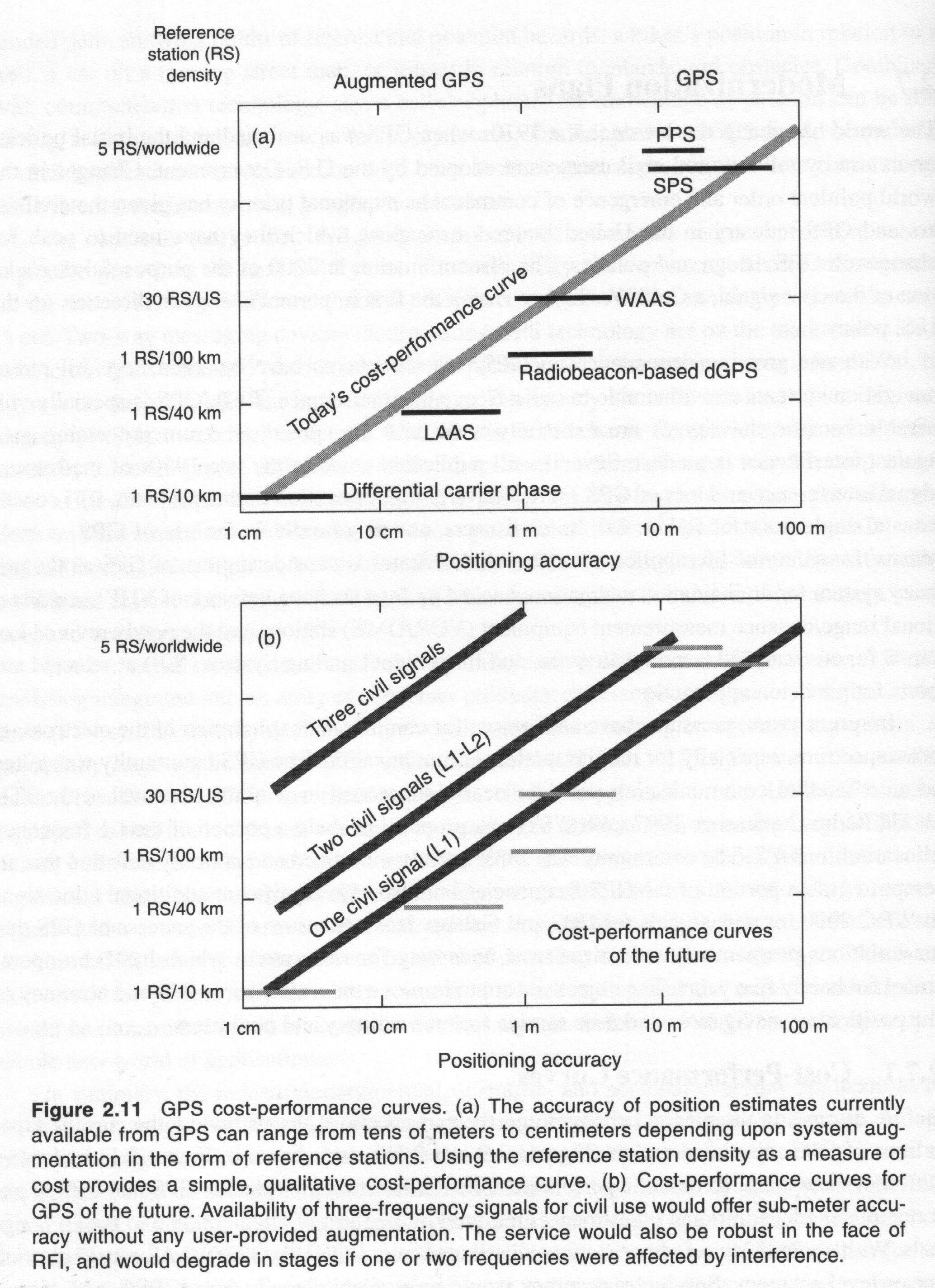
- For more precise applications it is necessary to get the
pseudoranges
from the carrier phases L1,L2-not the codes phases-, obtained by
integrating the frequency discrepancy regarding to the nominal one due
to the Doppler effect.
- The pseudorange
errors are typically 100-1000 times greater than those of the carrier
phase observation errors due to the smaller wavelength. Indeed
 is typically
  :
:  ,
,  ,
,  .
.
- The carrier phase introduces an additional unknown in the
models: the integer
ambiguity, which corresponds in unit lengths to the pseudorange at
the satellite lock epoch.
- The third type of signal used in GPS observations: the
navigation data
or broadcast message: subcarrier with
50 bits per second (bps), that
repeats (not all the frames) each 30 s.
- The navigation data is binary added to the code chip sequences.
- The signal structure permits both the phase and phase shift
(Doppler
effect) to be measured and the necessary bandwidth is achieved by phase
modulation (0 and 180 degrees, phase bimodulation) of the PRN
code and combining both codes in L1 by means of phase quadrature
(for the i-th satellite):


- Bandwidths of 20 MHz for P and 2 MHz for C/A.
- On the other hand the GPS signals are extremely week. The
satellite emits ~50W (50% for C/A), and the reception power
specifications at the Earth is -160 dBW (for C/A code; -163 dBW for
P(Y) in L1 and -166 dBW for P(Y) in L2), but the
real measurements are 3-5 dB higher than the expectations.
- Such receiver power of 10-16W is well below the
background RadioFrequency noise level. But this is not a problem
because this is compensated by the processing gain, coming from knowing
the signal structure (PRN code).
- Anyway the low signal power is the Achille's heel of GPS. In the
future this problem is mitigated with the frequency diversity and
increased signal power.

- Regarding to the signal acqusition and tracking, firstly the C/A
code is acquired, from a rough position and a recent almanac,
containing the rough ephemeris and clock information coming from the
overall GPS constellation. This can be done, easily due to the short
length of the C/A code (1023 chips @ 1.023 MHz, i.e. a chip period of
T=1ms, i.e. a chip wavelength of 300 km).
- After, from a known timing information between C/A and P1,
the P-code is acquired. The corresponding observables ("pseudoranges"
or "codes"), are obtained in the Delay Lock Loop (DLL) from the
apparent travel time from transmision to reception, scaled by the light
velocity.
- After DLL another feedback loop is working: the Phase Lock Loop
(PLL), which measures the Doppler shift which provides an observable
for estimating the velocity (presently with errors lesser than 0.1m/s,
in front of less than 1m/s when the S/A was activated).
2.5 The ephemerides structure

- Determination of the Broadcast Ephemerides:
- First, a reference ephemeris based on 7 days of
observations
from the control segment is generated (off-line).
- Second, this a priori orbit is corrected on-line
with
the incoming control segment observations by means of the Kalman
filter,
estimating:
- Six orbital elements per satellite
- Three clock parameters per satellite
- Three solar radiation pressure coefficients per
satellite
- Two clock parameters per monitor station (one is fixed
as the reference)
- One tropospheric scale factor per monitor station
- Three polar motion parameters
- The estimated perturbations are used to generate the
broadcast ephemeris
every hour (with discrepancies in the overlapping of
 m).
m).
- Time parameters:
-
 reference time, ephemeris parameters (s)
-
 reference time, clock parameters (s)
-
 polynomial coefficients for clock correction (bias(s),
drift (s/s), drift-rate (s/s
  ))
))
- IOD Issue of Data, artibrary identification number
- Keplerian elements:
-
 square root of the semi-major axis (m
  )
)
- e eccentricity (dimensionless)
-
 inclination angle at reference time (semicircles)
-
 longitude (not right ascension) of the ascending node at
reference time (semicircles)
-
 argument
of perigee (semicircles)
-
 mean anomaly at reference time (semicircles)
- Perturbation parameters:
-
 mean motion difference from computed value (semicircles/s)
-
 rate of change of right ascension (semicircles/s)
-
 rate of change of inclination (semicircles/s)
-
 amplitude of the sine harmonic correction term to the
argument
of latitude (rad)
-
 amplitude of the cosine harmonic correction term to the
argument
of latitude (rad)
-
 amplitude of the sine harmonic correction term to the
angle of
inclination (rad)
-
 amplitude of the cosine harmonic correction term to the
angle of
inclination (rad)
-
 amplitude of the sine harmonic correction term to the
orbit
radius (m)
-
 amplitude of the sine harmonic correction term to the
orbit
radius (m)
- The Satellite Time:
- The GPS time system is defined by the main clock in the
master control
station (MCS)
and starts at January 5, 1980 0h UTC (saturday to sunday midnight),
where the week number starts.
- It is usually indicated by the week number and the number of
seconds
of the week (0 to 604800 s).
- The leap seconds in the UTC time scale and the drift in the
MCS clock
are two differences between GPS time and UTC.
- The Satellite Coordinates computation will be discussed in the
next
chapter.

2.6 The GPS message structure
- The GPS navigation message has a cycle of 30 seconds, with a bit
rate
of 50bps (1500 bits):
- It is composed on 5 subframes (6 seconds, 300 bits each):
- The first subframe corresponds to the Datablock I (clock
parameters)
- The second and third subframes to the Datablock II
(broadcast ephemerides)
- The fourth and fifth subframes corresponds to Datablock
III (almanac,
UTC, ionosphere,..., each consists on 25 consequetive pages: 12.5
minutes in
total)
- Each subframe contains 10 data words (0.6 seconds, 30 bits
each):
the firt two are the telemetry word (TLM) and the C/A-P code
hand over word (HOW).
- The intentional limitation of the system accuracy:
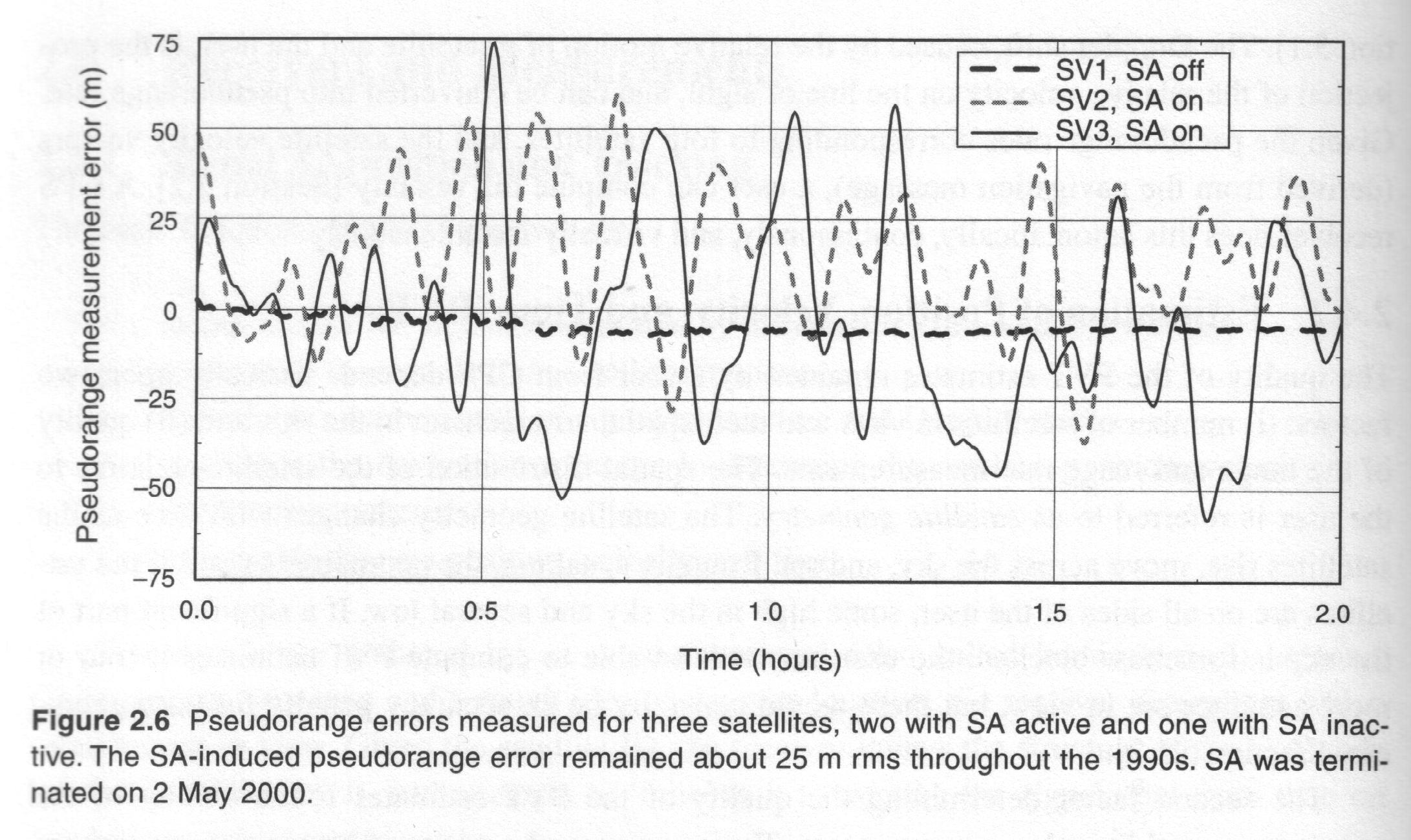
- The Anti-spoofing (A/S), the encryption of the P code in
L1,L2.
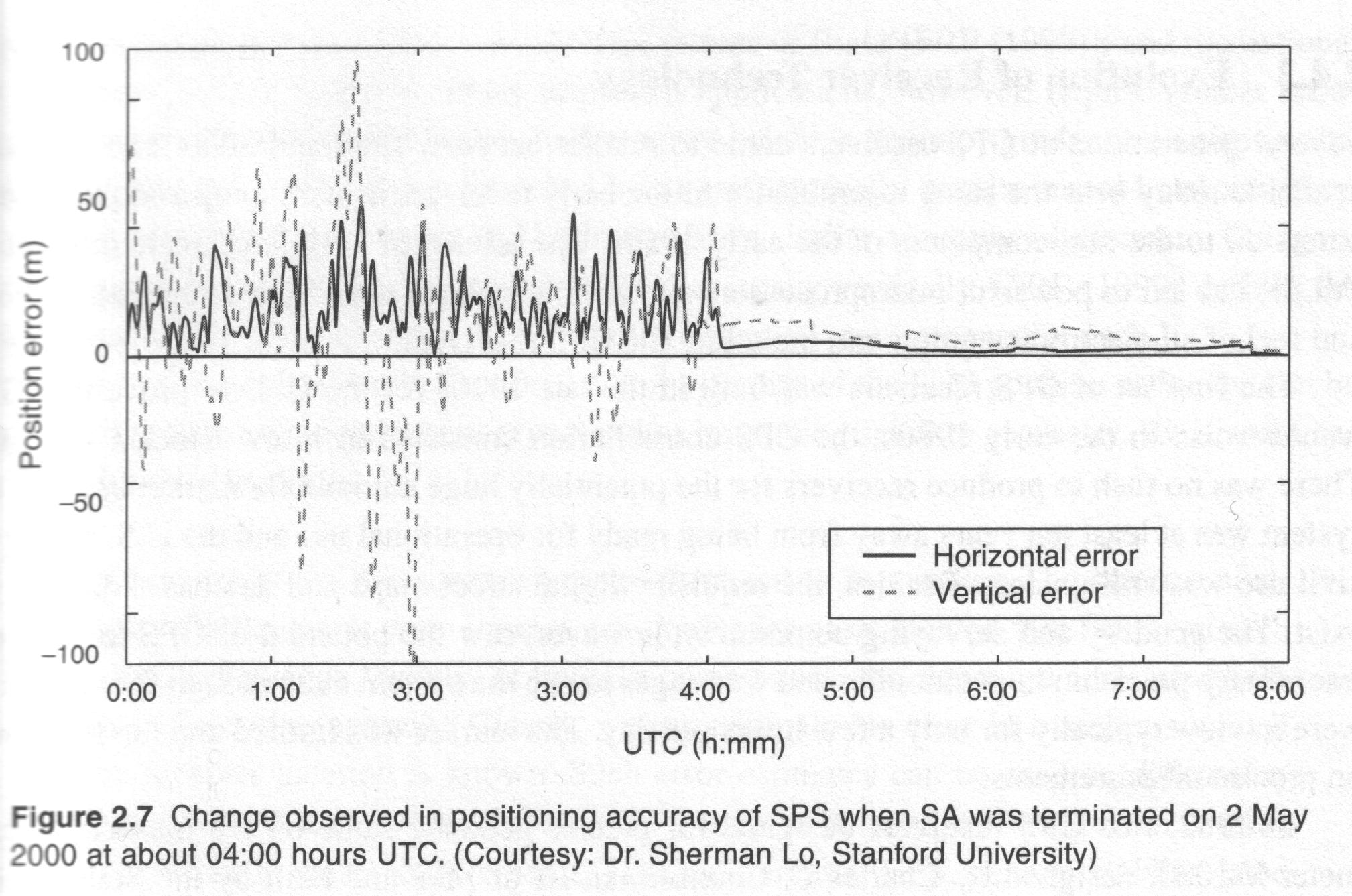
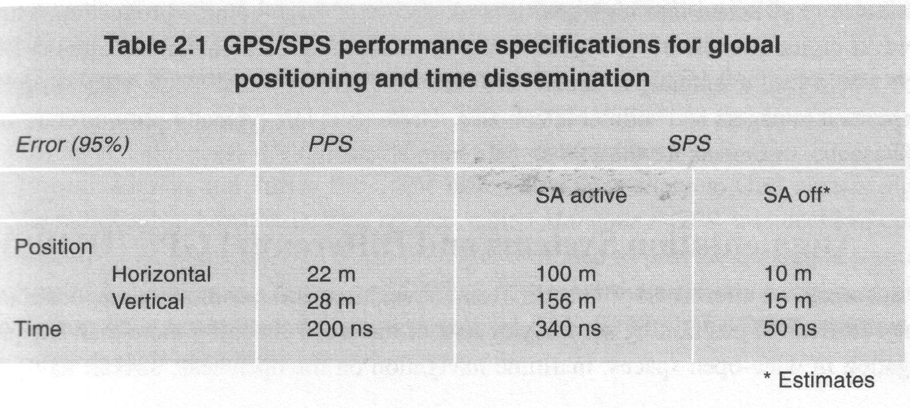
- The Selective Availability (S/A), with ephemeris data
manipulation
(
 technique)
and dithering or systematic destabilazing of the
satellite clock (
  technique).
2.7 The User segment
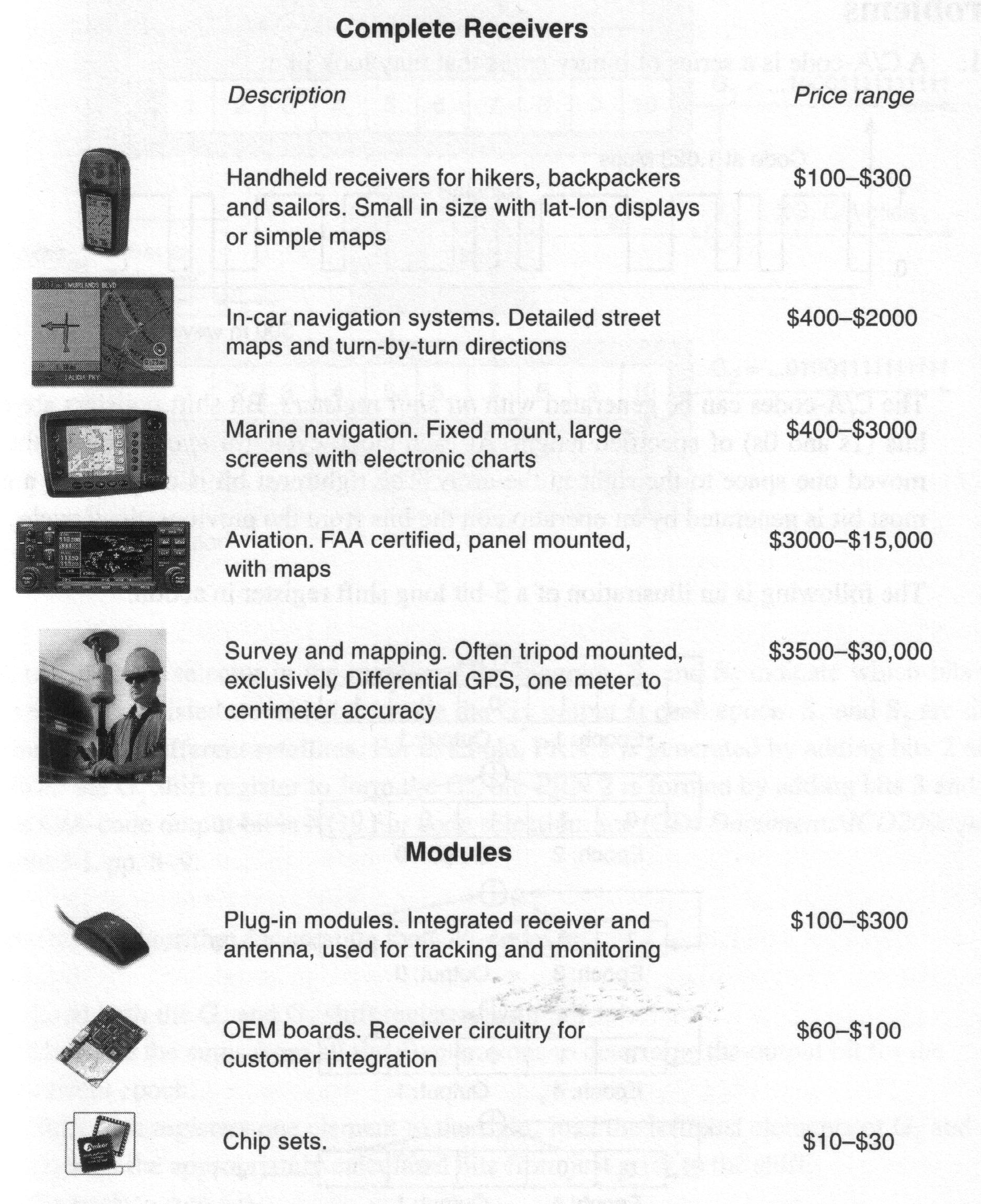
- The main components of a GPS receiver:
- Antenna with preamplifier
- RF section with signal identification and signal processing
(channel)
- Microprocessor for receiver control, data sampling, and data
processing (navigation solution)
- Precision oscillator
- Power supply
- User interface, command & display panel
- Memory, data storage
- Several types of GPS antennas:
- Monopole or dipole
- Quadrifilar helix
- Spiral helix
- Microstrip
- Choke Ring
- GPS receiver classification-1:
- Code correlation (code-dependent)
- Squaring (code-free)
- GPS receiver classification-2:
- Multi-channel
- Sequential
- Multiplexing
- GPS receiver classification-3:
- Military (Y1,Y2)
- Civilian (C/A,L1)
- Navigation (C/A)
- Timing (C/A,L1)
- Geodetic (C/A,L1,L2,
 )
)
2.8 Differential positioning
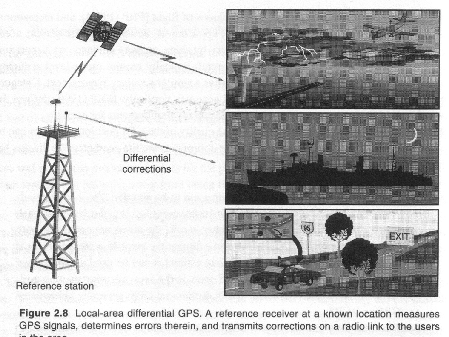
2.9 Modernized GPS and Galileo


Next:
III. Satellite Orbital Motion
Up: II. Global
Positioning System
Previous:
2.3 Control Segment
Manuel Hernandez Pajares
Thu Jun 4 14:25:37 GMT 1998


![]()
![]()


