![]()
Then:
![]()
In the resulting superposition, we have
the phase velocity ![]() for the carrier
phase and the group velocity
for the carrier
phase and the group velocity ![]() , the velocity of the transmitted
information:
, the velocity of the transmitted
information:

And from this expression we can relate the corresponding refraction indices
![]() and
and ![]() in terms of the frequency
dependences:
in terms of the frequency
dependences:
The Maxwell equations in integral form are:
And in differential form:
And from 14 in the vacuum with ![]() ,
, ![]() ,
,
![]() the equation of the EM wave with propagation velocity
the equation of the EM wave with propagation velocity
![]() can be obtained:
can be obtained:


![]()
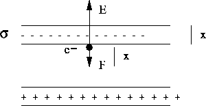
And the movement equation is then harmonic:
![]()
with associated frequencies for electrons and ions respectively:
![]()
with frequencies respectively related as:
![]()
For the second kind of movement, due to the Earth magnetic field, we have a typical spiral path due to the Lorentz force:
![]()
where ![]() is the Larmor frequency, which are related, between ions and
electrons as:
is the Larmor frequency, which are related, between ions and
electrons as:
![]()
| Ion |
|
|
|
|
|
| | | 0.02 | |
|
| 762 | | 1.0 | |
|
| 47.7 | | 4.1 | |
|
| 25.4 | | 5.7 | 909 |
|
| 23.8 | | 5.9 | 879 |
Finally to say that the answer of the plasma to the simultaneous
![]() and
and ![]() is
is ![]() being the velocity
of the colisionless guide center:
being the velocity
of the colisionless guide center:
![]()

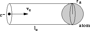
From here, the corresponding colision frequency can be approximated as:
![]()
whith typical values of ![]() s
s ![]()
An approximated expression is:
![]()
![]()
and the movement equation for the free electron (we neglect the magnetic field):
![]()
One solution for the velocity is:
![]()
From these equations, we can get:
![]()
The resulting current density ![]() is:
is:
begin ![]() the ionospheric free electron density.
Now applying the third Maxwell equation in 14:
the ionospheric free electron density.
Now applying the third Maxwell equation in 14:
![]()
and assuming an isotropic medium (the vacuum):
![]()
and the equation 16, we get:
![]()
This equation can be rewritten as:
![]()
being
![]()
From here, the phase refraction index ![]() can be written as:
can be written as:
being ![]() in electrons/m
in electrons/m ![]() and f in Hz.
and f in Hz.
From equation 11 the group refraction index ![]() is
is
And finally the ionospheric delay produced in the code, ![]() , will be:
, will be:
being ![]() and
and ![]() the position vector of the receiver and
satellite j.
Substituting equation 18 in 19 and taking into account
17 we reach to the following relationships:
the position vector of the receiver and
satellite j.
Substituting equation 18 in 19 and taking into account
17 we reach to the following relationships:
where ![]() is the Slant Total Electron Content (STEC)
along the raypath between
the given receiver and the transmitter j.
is the Slant Total Electron Content (STEC)
along the raypath between
the given receiver and the transmitter j.
From here, the ionosphere positive/negative delay for the GPS code/phase
can be written for both frequencies ![]() and
and ![]() as:
as:

And from here it can be eliminated the ionosphere term in the "ionospheric-free" combinations PC, LC or to isolate the ionospheric dependence for mapping purposes with the "ionospheric" combinations PC, LI:

where the last expressions for ![]() and
and ![]() is for the STEC
in units of
is for the STEC
in units of ![]() electrons/m
electrons/m ![]() and the delay in meters, including also
the instrumental biases for the transmitter and receiver.
and the delay in meters, including also
the instrumental biases for the transmitter and receiver.
![]()
where n is the refraction index and N is the refractivity (the same for both code and phase in an non-dispersive medium).
To get a model for the dependence of N with the height h, we are going to assume that:
![]()
where M is the molar mass, P is the pressure, T is the temperature, R is the Rydberg constant and h is the height.
Applying the hydrostatic law for the pressure
![]()
and the hypothesis of temperature gradient constant,
![]()
then,
![]()
.
From these last relationships, we can integrate:
![]()
![]()
And:

being ![]() the root height,
the root height,
![]() and
and ![]() the refractivity in h=0, that for the
hidrostatic (dry) and wet components are respectively
the refractivity in h=0, that for the
hidrostatic (dry) and wet components are respectively ![]() ,
, ![]() :
:
![]()
![]()
where e is the water vapour pressure.
The Hopfield model is an empirical realization of our model 21
( ![]() 6.71 C/km):
6.71 C/km):
![]()
To relax a bit the hypothesis, we will allow a certain dependence of
![]() with the temperature:
with the temperature:
![]()
Then, we can get the tropospheric vertical delays:
![]()
with:
![]()
![]()
And finally, in order to relate the vertical delay with the slant delay, we have to apply an oblicuity factor usually named mapping function M, that depends on the elevation angle E:
![]()
It can be approximated for high elevation with the cosecant funcion, corresponding to the plane-parallel approximation of the atmosphere:
![]()
Some mapping functions used, for the hydrostatic and wet delay, are:
![]()
If we want to avoid the tropospheric modelling with GPS, we need to have a close reference GPS receiver and to perform differential GPS (DGPS).